


Solutions
Horse Construction offers full range of structural strengthening materials with technical supports, documentation supports, products supports, project supports.
Bridge Structure Cracks And Reinforcement Technology

1 Project Overview
A bridge is connected with the common line of 318 National Road and 206 National Road through an interchange. The bridge crosses the urban area and has a total length of 6.24km. The main bridge is designed as a five-span continuous double-tower cable-surface steel box girder cable-stayed bridge. The main bridge has a total length of 1.04km. The tender section of this treatment is K20+118—K20+648. The main bridge adopts flat streamlined fully welded closed steel box girder, and the beam height at the center line of the bridge is 3.0m. There are a total of 16 pairs of 64 double-cable-plane fan-shaped steel strand stay cables, which are anchored to the steel box girder at a standard distance of 15m. The anchorage distance on the pylon is 2.5m, and the stay cables are stretched at the tower end. The pylon is a reinforced concrete separated Y-shaped pylon with a total height of 185m. The tower height above the bridge deck and the main span ratio are 0.2651. The upper tower column is designed as a separate single-box single-cell polygonal section. The upper, middle and lower three beams of the tower are all prestressed reinforced concrete structures. The bridge was completed and put into operation in 1996. With the increase in service life and the continuous increase of traffic volume, the concrete structure surface of the bridge main body, pylons and tower columns began to appear cracks of different degrees. In order to ensure the performance and service life of the bridge, cracks must be reinforced.
2 Mechanism and causes of structural cracks
Concrete basic materials have a wide range of applications in the current bridge structure construction, with the largest number of applications, and there are large changes in material properties, shapes and strengths according to different mix ratios, and they have strong durability and life potential. However, the stone, brick, steel, concrete and other materials that make up the bridge structure have weak tensile strength, and slight tension will cause cracks. Therefore, the occurrence of cracks is almost inevitable. The existence and later development of cracks will weaken structural members and load-bearing capacity to varying degrees. In addition, the cracks in the bridge structure can also cause the protective layer to fall off, the corrosion of steel bars, the carbonization of concrete materials, the decrease of structural durability and strength, and even shorten the service life of the bridge, affecting the normal use of the bridge.
The mechanism that causes conventional cracks in bridge structures is relatively complicated, and single-factor cracks are relatively rare. Cracks are usually caused by one or several factors, and the remaining factors only cause the cracks to continue to develop or increase the cracking. Therefore, when analyzing the causes of cracks, the form of cracks must be correlated with the causes. Specifically, the causes of bridge structural cracks include the following aspects.
2.1 Load cracks
The bridge concrete structure is prone to load cracks under the action of conventional dynamic and static load and bridge secondary stress. Load cracks are usually directly manifested as direct stress cracks and secondary stress cracks. Direct stress cracks are mainly caused by the surface load of the bridge exceeding the stress range that it can bear, and secondary stress cracks are caused by the influence of external load on the bridge structure and cause the cracks to appear.
2.2 Self-stressing cracks
Self-stress cracks in bridge structures include cracks caused by bridge structure shrinkage and cracks caused by temperature differences.
2.2.1 Structural shrinkage cracks
The uneven shrinkage of the bridge concrete structure inside and outside during the solidification process causes the surface pressure to be far greater than the range of tensile strength, which leads to cracks in the bridge structure. Under normal circumstances, the 4 hours after pouring of the bridge concrete structure is the most intense and active stage of the cement hydration reaction, and it is also the critical period for the generation and formation of the molecular chain of the concrete structure. The process of molecular chain formation must be accompanied by bleeding, which also indicates that the concrete structure has not completely hardened, causing plastic shrinkage. Since then, as the concrete structure continues to harden, the surface bleeding continues to evaporate, the temperature gradually decreases, the volume of the concrete structure decreases, and shrinkage cracks appear.
2.2.2 Temperature cracks
Exotherm occurs during the solidification of the concrete structure, and the welding arc causes temperature changes and strong light. The above temperature changes will cause expansion and contraction to occur alternately. As a result, the temperature stress far exceeds the strength that the concrete structure can withstand, causing structural cracks. Taking into account the geographical environment of the bridge project, there are certain changes in the temperature difference every year, which continuously triggers the longitudinal displacement of the bridge. The local temperature of the sides and pillars of the bridge body rises after direct sunlight, and the local tensile stress in this part will increase, causing longitudinal cracks.

2.3 Material reasons
This bridge is mainly a concrete structure. When analyzing the causes of cracks in the bridge structure, it was found that the design and construction stage of the concrete material mix ratio was unreasonable, resulting in a decrease in the tensile strength of the concrete material and cracks in the concrete structure. Due to the shrinkage characteristics of concrete materials, it is very sensitive to temperature changes, and the temperature difference changes during the construction stage.
2.4 Improper maintenance
Since the bridge was built and put into operation, it lacked reasonable maintenance and management, and did not impose strict restrictions on the passage of overloaded and over-limit vehicles. Over time, the bridge was overloaded and caused structural cracks.
3 Reinforcement of cracks in bridge structure
A lot of engineering practice shows that cracks in concrete structures are inevitable, and some cracks are harmless or controllable. If the requirements for structural crack resistance are too high, the construction cost of the project will inevitably increase. According to the specific purpose and performance requirements of the project, the degree of damage of the cracks should be scientifically controlled within the allowable range.
3.1 Improve the bridge design
In order to fundamentally solve the problem of cracks in the bridge structure, it is necessary to strengthen the scientific design of the bridge structure, combination method and material application from a design perspective, and accurately calculate the load borne by the bridge. And strengthen the management of various construction materials and mechanical equipment, improve the construction methods, and supervise the construction unit to carry out construction in strict accordance with the design drawings and design procedures. For example, the continuous curing of construction materials accelerates the hydration reaction of concrete materials, ensures the improvement of material strength, reduces material shrinkage and creep, and prevents the occurrence of cracks. At the design stage, the weather conditions, ambient temperature, sunshine, temperature difference and other possible adverse effects on the bridge structure during the construction period should also be fully considered, and the fatigue strength of the bridge structure under mechanical vibration should be checked.
3.2 Crack repair treatment technology
Repairing cracks in bridge concrete structures should promote the restoration of the waterproof performance and durability of the structure. If the concrete structure has serious diseases, it should be repaired before reinforcement, including the following measures.
3.2.1 Surface pasting repair or spraying
(1) Surface paste repair
For micro-cracks in bridge concrete structures with a width of less than 0.2mm, you can paste glass cloth or steel plates on the surface and apply fillers and waterproof materials to improve the waterproof performance of the structure and prevent the cracks from expanding further. Before the FRP cloth is pasted, gouge the surface of the cracks and scouring. After reaching a certain level of flatness and cleanliness, apply the epoxy-based liquid evenly on the entire pasting surface, then straighten the FRP and paste it, smooth it and fix it with a brush. . Before the steel plate is pasted, the steel plate should be cut according to the size of the crack and polished until the steel bar is exposed. After the crack is repaired, a layer of epoxy-based liquid adhesive is applied to the surface to facilitate firm bonding.
(2) Spraying repair
The surface of the cracks in the concrete structure is shaved and sprayed with a dense, high-density cement mortar protective layer to achieve the purpose of sealing the cracks and strengthening treatment. Before spraying the cement mortar, the peeling layer on the surface of the structure must be thoroughly removed and rinsed thoroughly with water to ensure that the base layer is wet and sprayed.
3.2.2 Pressure grouting
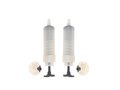
Delineate the repair scope according to the specific conditions of the crack, determine the location of the hole and the amount of slurry, and the hole before the crack must be operated along the crack, and ensure that the surface of the crack and the axis of the hole are at an angle of more than 30°. After the drilling is completed, clean water is injected along the hole for cleaning, and the drilling is blown dry with compressed air, the pre-prepared grout is poured into the concrete and then the grout repair construction is carried out through the grouting pump. For non-penetrating cracks, it is difficult for the grout to be injected into the structure, and excessive injection pressure may expand the width of the crack. For this reason, low-pressure and low-speed grouting should be used for cracks in bridge structures, which can not only control the amount of grouting, but also ensure that the grout is injected into the deep part of the crack. If epoxy resin is used as the grouting material, the viscosity of the epoxy resin material should be fully considered. In order to ensure that the grout is fully poured into the cracks, the amount of solvent can be increased, but an excessive amount of solvent will reduce the viscosity of the grout and it is difficult to achieve the expected filling and bonding purpose. The deformation tracking properties of epoxy resin will deteriorate in extended cracks, and flexible epoxy materials should be used for such cracks. According to a large number of engineering practices, the combination of epoxy resin material and steel claw nails can enhance the integrity of the structure after reinforcement of cracks, and can effectively prevent the subsequent cracks.
3.2.3 Grouting and filling
That is, by injecting cement, resin and other materials into the concrete structure cracks, the durability and waterproofness of the structure are effectively improved, and it is suitable for wider cracks with a width of 0.5mm or more. First, a deep groove is cut along the crack, and then cement mortar, epoxy mortar, asphalt, reinforcing agent and other bonding materials are embedded in the groove. For reinforced concrete structures with uncorroded steel bars, the concrete structure should be chiseled into a U-shape along a width of 10 mm at the crack and filled with sealing materials for crack repair. If the steel bar has been corroded, the concrete structure should be removed to the entire corroded part. After the steel bar is derusted, anti-rust paint should be applied, and the sealing material should be filled to repair the crack.
3.3 Reinforcement technology of beam structure
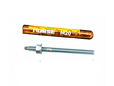
The reinforcement of the upper structure of the beam bridge should be based on the actual conditions of the bridge and the degree of reduction in bearing capacity. Under normal circumstances, the strength of the structure can be improved by enlarging the section of the original member; replacing the old structure with a new structure to improve the resistance of the structure; changing and optimizing the force system of the original structure to reduce the peak torque of the control section. Prestress is applied to change the original structure's force system and improve the rigidity of the structure. You can choose to increase section reinforcement technology, external paste reinforcement technology, external prestress reinforcement technology, structural system reinforcement technology, additional longitudinal beam reinforcement technology, etc.
4 Conclusion
The factors that cause bridge structural cracks are more complicated. Only a comprehensive and systematic analysis and study of the causes of cracks, mastering the mechanism of causing bridge diseases, and assessing the degree of crack damage can provide decision-making basis for the response and reinforcement of bridge structural cracks. Although the current problem of bridge structural cracks is relatively common, as long as the mechanism of bridge structural cracks is fully understood and mastered during the design and construction stages, and economic and effective reinforcement treatment technology is adopted, the occurrence of bridge structural cracks can be reduced or even avoided.
You can find anything here you are in need of, have a trust trying on these products, you will find the big difference after that.

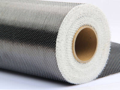
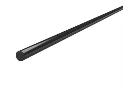
High strength, unidirectional carbon fiber wrap pre-saturated to form a carbon fiber reinforced polymer (CFRP) wrap used to strengthen structural concrete elements.

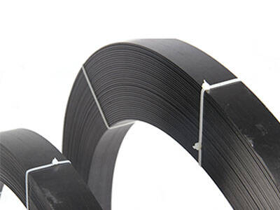
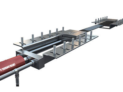
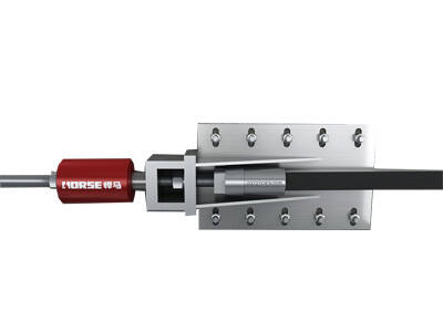
Prestressed carbon fiber reinforced polymer(CFRP) plate for slab, beam strengthening to increase stiffness, reduce distortion and deflection of members, reduce the cracks, avoid and stop cracking.

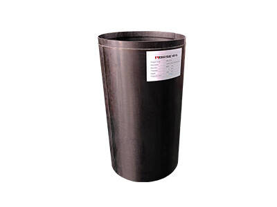
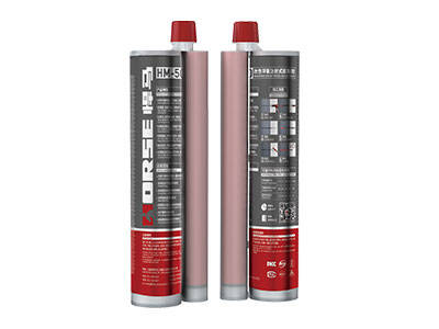
Very strong penetration and low viscosity epoxy crack injection adhesive for repairing concrete crack
